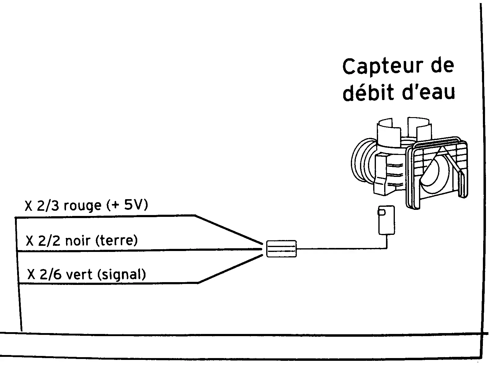
This diagram is from the service manual of a combi boiler. It’s a flow sensor which detects whether hot water is running, which is then used to trigger on-demand heat and switch a diverter to take radiators out of the loop.
In English, the diagram shows:
- X ⅔ red wire (+5V)
- X 2/2 black wire (ground)
- X 2/6 green wire (signal)
I need to know what those fractions mean. I took the voltage measurements in this video:
I cannot necessarily trust the model in that video to have the same specs as mine. My voltmeter detected 4.68 V on the red input wire showing that the sensor is well fed. The green “signal” wire is supposed to be 0 V at rest and 2 V with water running (or I think the reverse of that is used in some models). In my case the green wire is ~1.33 V at rest and ~0.66 V when water is running. I need to know if these readings are normal as I troubleshoot this problem.