Maybe there’s something I don’t understand here. I’d love it if someone told me how to do the following.
Let’s say I have some really complex shape in a sketch left of the Y axis: it takes me forever to get it just right. Then I need to mirror it on the right side of the Y axis and connect the two halves.
In SolidWorks, it’s trivial: mirror the stuff, done. If you change the master shape on the left, the change is reflected on the right.
In FreeCAD, the best you can do is make a mirror copy of the left-hand side elements - which also makes copies of the constraints which are completely independent from the original constraints on the left-hand side - delete the stupid new right-hand side constraints and slowly, painfully constrain the right-hand side copies to the original left-hand side elements, trying to dodge the dreaded orange over-constraints all the time. It’s long, it’s painful, and the end-result is usually so fragile that if you change anything significant on the left-hand side, the sketch turns orange and then it’s back to hunting broken constraints again.
Surely it can’t be that painful. Am I missing something obvious?


I feel like this is not how it works for me. It does copy the constraints and automatically create symmetry between any points across the selected center line, but if you’re making a mirror why is that not what you want?
Also I’m unsure about the behavior in older versions of freecad, the constraint behavior of this feature is new in 1.0
I’m using the daily build.
When I use the sketcher symmetry tool, here’s how it works for me:
Say I create a rectangle on the left. I use the tool, it creates 4 segments on the right with 2 horizontal constraints, 2 vertical constraints, copies of the horizontal and vertical dimensions, and zero relationships with the original elements on the left. I basically have to delete all the new constraints and add symmetry constraints manually.
Here’s how it works for me: https://vimeo.com/1019673822
Sorry I forgot to click record cursor. But hopefully that’s clear enough.
Thanks!
Oh wow yeah, that’s more like it. Totally not what I’m getting.
I guess I’m gonna have to dig into the settings, see if something controls the tool’s behavior. Or possibly wipe my config and start afresh, see if I might have inherited some settings from an old 0.22 beta or something.
Okay so not perfect, like you said, but at least I know I should be able to get something workable.
Also, unrelated, but you must be the first person I’ve seen post a Vimeo link in the past 10 years. And I’m not even exaggerating 🙂
lol, I just stuck with it I guess 🤣. Seems to work fine
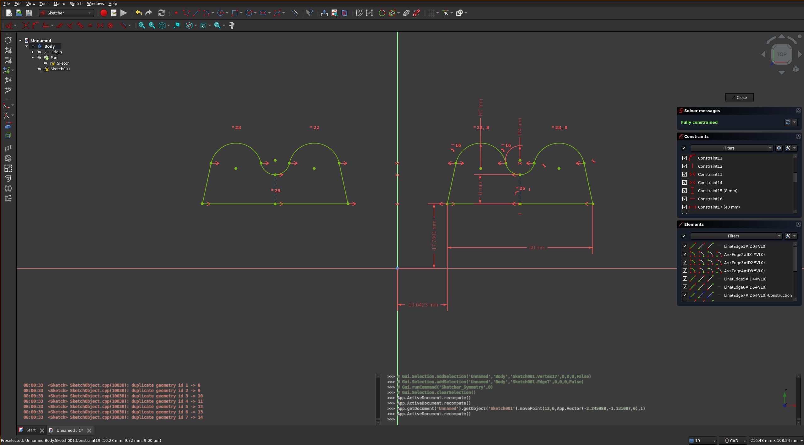
FWIW, this is what I get when I try to mirror a complex sketch:
https://toobnix.org/w/njayYNd5vE1HKNM3XVqYNM
Really not what I want.
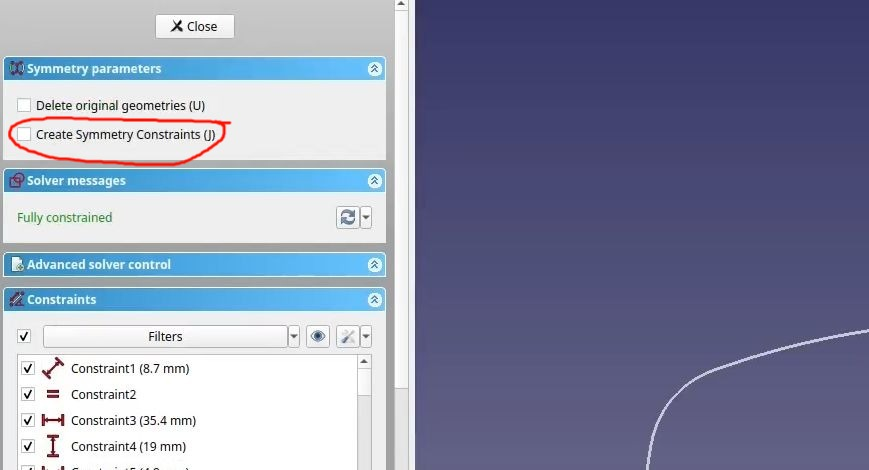
You didn’t select “Create Symmetry Constraints”. I’m not sure if it will solve the issue completely, but it will probably make some difference.
One thing I see that may come back to bite you later: You can create sketches that make multiple bodies when padded, but I’m not sure why you would want to with the example in this video. If the sketch is two identical bodies mirrored across an X/Y/Z plane use the part design mirror feature and offset the sketch’s attachment not the geometry in the sketch. It works better for that and keeps your sketches simpler, and you get to use symmetry for one side of the two things you are making because the origin will be in the center of one of the objects.
Sketches where the origin of the sketch isn’t the approximate center of a single closed wire are annoying later if you want to reference them in other features or sketches.
Are you making sunglasses? 😎
Oh…
Damn I feel stupid. I totally missed that somehow.
Thanks a lot, you rock! I learned something new today. I guess it was worth asking the question after all 🙂
No, I’m making regular frames for a friend because he saw the ones I made for myself a couple days ago and he asked whether I could print him new frames to reuse his old lenses.
I just used that sketch for the example.
Ah, I see. I imagined your use of that sketch differently. Looks good!
When I do what you did but select “Create Symmetry Constraints” I get a fully constrained result as soon as the Sketcher Symmetry tool is finished. No other action is required.