
Hello, we are making a thesis where we use MOSFETs as an alternative radiation detector. So to explain it, it works when the mosfet is irradiated with an external radiation source; its voltage threshold increases, which will be used to determine the radiation dose. I’m currently asking for help on how we measure the voltage threshold. BTW, we are using an n-channel MOSFET (model: IRFP250NPbF). Also in the datasheet provided by the manufacturer, it says here VGS(th)/Gate Threshold Voltage Min: 2.0 ––– Max: 4.0 V. There is a condition here with VDS = VGS, ID = 250 A. Does this mean that to measure the VGS, we need to first satisfy the conditions? To measure the voltage threshold, what node will we use to measure the VGS (th)? Is it at the drain to the source terminal or still at the gate to the source terminal? Feel free to share your thoughts, if you have any. I would also like to add that we have already tried to supply a voltage at the gate with respect to the source terminal. We use a 4 V supply voltage, and when we tried to measure the VDS (drain to source voltage), there was a voltage drop, so we’ve got a 3.5 V. Also, we are using an Arduino to measure its voltage and a multimeter for checking.
Using MOSFETs as TID sensors is common enough. A term that you can use for more research is RADFET. The best way to measure threshold voltage is to sweep the gate voltage. In my experience however, if you intend to measure this in a non-lab environment (say, in a satellite), I would recommend that you instead connect the gate to the drain, force a small constant current (maybe 10uA) from the drain to source, and measure Vds (which is equal to Vgs in this configuration). This won’t give you the threshold voltage per se, but this will produce a voltage that changes as dose accumulates, is a far easier metric to measure, and is as equally valid as measuring the threshold voltage to determine TID. You can’t really predict the shift in threshold voltage according to TID unless your MOSFETs are all from the same batch (manufacturing defects and tolerances), and you need to calibrate them in order to obtain a calibration curve (this is done by simply going to irradiate several (the more the better, I suggest at least 10 for statistical significance). Alternatively, you can buy pre-calibrated ones from companies who make MOSFETs for this intended purpose like Varadis. If you really want to measure the threshold voltage, you could read MIL-STD-750, which outlines how to measure the threshold voltage.
Hello, do i still need to apply a supply voltage of Vgs, or will only the current at the drain be the main source. Also, is this MOSFET sensitive enough for a cs-137 (661 keV).
Ultimately, yes you will need to bias the gate. If you put the MOSFET in the diode connection mode, the gate will automatically be biased when you force a constant Ids current. While I have never worked with this MOSFET nor with Cs137, I don’t see why it wouldn’t be sensitive. A few notes:
Also i’m using a TO-92 package for a MOSFET, so is there any tips on the orientation during the irradiation.
I’m not entirely sure, but I suspect that the die is mounted to the leadframe on the flat side of the package. In this case you should point the flat side towards the source.
I’m using lm334z as a current source, i’m still thinking and deciding on where to connect it to the MOSFET. Can you propose the wiring for the current source input once the MOSFET is in diode connection. Like for example, in a breadboard i used a wire to connect the drain and gate. then, i’ve applied a constant current at drain terminal with source connected to the negative. So to check the change in voltage, should i measure the voltage in Gate to source?
The wiring is simple enough, see image. Since the gate is connected to the drain, you can measure either Vds or Vgs. They are equal in this configuration so it doesn’t matter.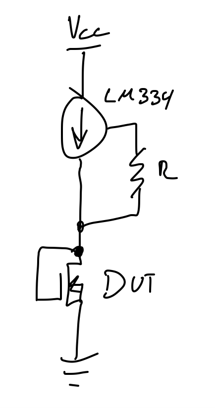
Hello, I have already tried to apply a microampere current (around 40 μA) using only Ohm’s law. I used a 2V input and a resistor in series. However, the LM334z is not working, and I am unsure of the reason for its failure. Will using an input voltage and a resistor in series work just fine?
I have also measured the Vgs, which reads at around 0.117 mV. What do you think about the measured Vgs? Technically, it should be around these values, right? Considering that there is a very small current.
You will probably need to increase your voltage. I haven’t ever used the LM334, but it will need a minimum voltage across it. I don’t know if you are still using the IRFP250N, but if so it has a threshold somewhere between 2V and 4V for 250uA, so the threshold won’t be as high but it should be close. I would try using 5V if it’s fine with your setup.
For the suitability of the resistor method, you should do the math on how a change in Vds will affect the current, and then calculate how much this variability in current will affect your readings. If this error/innacuracy is acceptable, then why not.
I just want to ask some points:
You will need to provide a voltage of at least the threshold voltage PLUS the minimum voltage of the LM334Z. If the LM334Z circuit by itself doesn’t work, that will be the first problem to figure out. Make sure you completely read through the datasheet https://www.ti.com/lit/ds/symlink/lm334.pdf?ts=1689139734046&ref_url=https%253A%252F%252Fwww.google.com%252F, there are example circuits in it for reference. For the resistor method, keep in mind that the current isn’t constant; the voltage is. Your current is dictated by your resistor and the voltage across it, which is the supply voltage minus the threshold voltage. If your threshold voltage changes as the dose increases (which is the typical behaviour), the voltage across the resistor will change, therefore your current will change, which will generate error in your reading. The only way to minimize this error is to apply a very high voltage (100’s to 1000’s of volts) to the resistor, such that a change in the threshold would become a rounding error.