• 0 Posts
  • 8 Comments
Joined 1 year ago
cake
Cake day: June 9th, 2023

help-circle
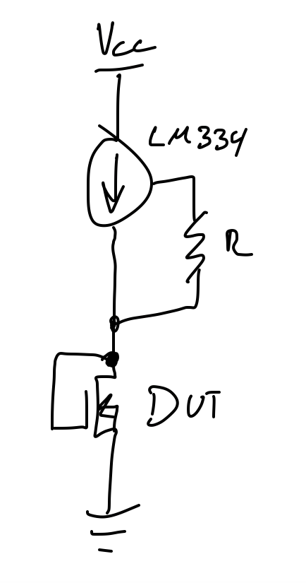
  • You will need to provide a voltage of at least the threshold voltage PLUS the minimum voltage of the LM334Z. If the LM334Z circuit by itself doesn’t work, that will be the first problem to figure out. Make sure you completely read through the datasheet https://www.ti.com/lit/ds/symlink/lm334.pdf?ts=1689139734046&ref_url=https%253A%252F%252Fwww.google.com%252F, there are example circuits in it for reference. For the resistor method, keep in mind that the current isn’t constant; the voltage is. Your current is dictated by your resistor and the voltage across it, which is the supply voltage minus the threshold voltage. If your threshold voltage changes as the dose increases (which is the typical behaviour), the voltage across the resistor will change, therefore your current will change, which will generate error in your reading. The only way to minimize this error is to apply a very high voltage (100’s to 1000’s of volts) to the resistor, such that a change in the threshold would become a rounding error.


  • You will probably need to increase your voltage. I haven’t ever used the LM334, but it will need a minimum voltage across it. I don’t know if you are still using the IRFP250N, but if so it has a threshold somewhere between 2V and 4V for 250uA, so the threshold won’t be as high but it should be close. I would try using 5V if it’s fine with your setup.

    For the suitability of the resistor method, you should do the math on how a change in Vds will affect the current, and then calculate how much this variability in current will affect your readings. If this error/innacuracy is acceptable, then why not.


  • For avionics, I doubt that they would use a traditional os. As far as I’m aware, Microsoft doesn’t have safety-certified builds of Windows with a real time kernel. Certifying a Linux build would also be a huge and costly endeavor. What they are likely using is a certified RTOS, like Vxworks, RTEMS, ThreadX, SafeRTOS, etc., or even Ada with the Ravenscar profile. You don’t really “develop” applications for these, you instead incorporate them as libraries inside your application and compile the RTOS into your application, and then run it on bare metal. Infotainment systems on the other hand will use more traditional OSes.

    A lot of the presentation seems to be rather typical of the aerospace industry, which is all about safety. Im not too convinced that this is due to Boeing being Boeing, but rather that DO-178 compliance is a bitch, ITAR can be another bitch, and certifying not only a single build of the Linux kernel but also an entire distro build will be a superhuman effort. At best it’ll take a long time with a sizeable team. Not sure that would Boeing be filling to fund that.


  • Assuming that this is a 10MHz reference, at the extreme your reference is 0.003Hz off from nominal (3e-10, or 0.3ppb error). It varies by 0.08ppb in the plot. IDK what it is that you bought (TCXO, OCXO, whatever), but that’s rather impressive stability. Depending on what type of oscillator it is you can expect a temperature coefficient anywhere in the several ppm to 0.1ppb. Do you know by how much the ambient temperature (or even better, the oscillator temperature) changed over the duration of the plot? I don’t work with temperature-compensated oscillators very often, but I don’t see an issue here.


  • Ultimately, yes you will need to bias the gate. If you put the MOSFET in the diode connection mode, the gate will automatically be biased when you force a constant Ids current. While I have never worked with this MOSFET nor with Cs137, I don’t see why it wouldn’t be sensitive. A few notes:

    • This MOSFET is in a TO-247 package, so make sure that you have the front of the MOSFET pointed towards the Cs137 source during irradiation, otherwise the leadframe will likely act as an attenuator, reducing the sensitivity.
    • This MOSFET is a HEXFET, which normally aren’t designed for continuous high DC power dissipation (they are meant for switching). So keeping the dissipated power in the FET would be best.
    • I’m not sure if there is a difference in general sensitivity between HEXFETs and other MOSFET types like VDMOS or traditional monolithic planar MOSFETs.
    • I’m not sure if you already planned this, put generally it is recommended for the MOSFET to have all pins grounded during irradiation. Biasing of the MOSFET can affect its sensitivity (depends on every MOSFET), so having all pins grounded keeps them in a constant state during irradiation (and lets all accumulated charge get shunted to ground, preventing ESD damage).

  • Using MOSFETs as TID sensors is common enough. A term that you can use for more research is RADFET. The best way to measure threshold voltage is to sweep the gate voltage. In my experience however, if you intend to measure this in a non-lab environment (say, in a satellite), I would recommend that you instead connect the gate to the drain, force a small constant current (maybe 10uA) from the drain to source, and measure Vds (which is equal to Vgs in this configuration). This won’t give you the threshold voltage per se, but this will produce a voltage that changes as dose accumulates, is a far easier metric to measure, and is as equally valid as measuring the threshold voltage to determine TID. You can’t really predict the shift in threshold voltage according to TID unless your MOSFETs are all from the same batch (manufacturing defects and tolerances), and you need to calibrate them in order to obtain a calibration curve (this is done by simply going to irradiate several (the more the better, I suggest at least 10 for statistical significance). Alternatively, you can buy pre-calibrated ones from companies who make MOSFETs for this intended purpose like Varadis. If you really want to measure the threshold voltage, you could read MIL-STD-750, which outlines how to measure the threshold voltage.